From Old Laptop to Family Calendar
During our normal spring cleaning, I came across an old laptop my wife used in college. By now it’s almost useless as a computer – the battery was shot, the CMOS battery had died, the heatsink didn’t work, the hard drive was small and slow… but I wasn’t ready to give up on it. Most of the parts still worked, if a little more slowly than their modern counterparts. That’s when I decided that, rather than scrapping the machine as a whole, I would disassemble it and use the parts in other projects.
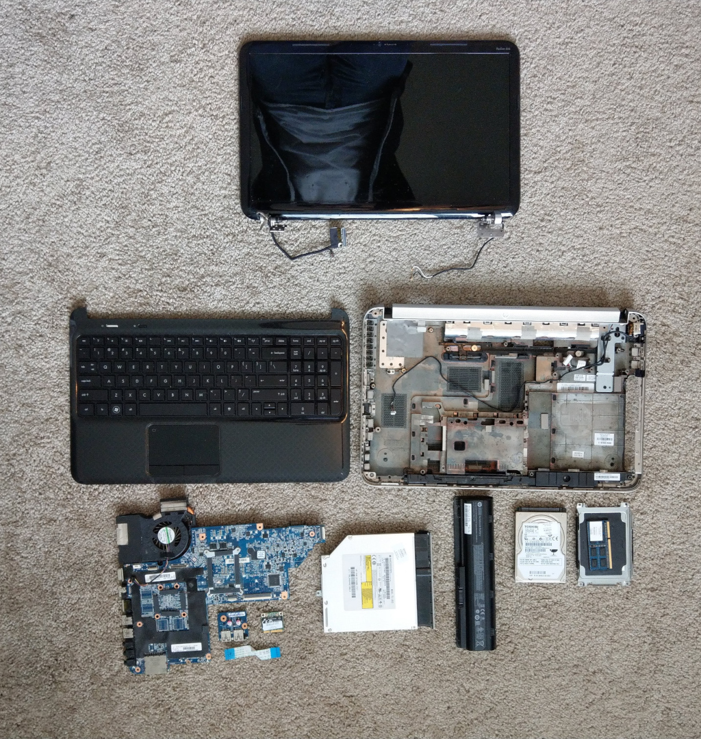
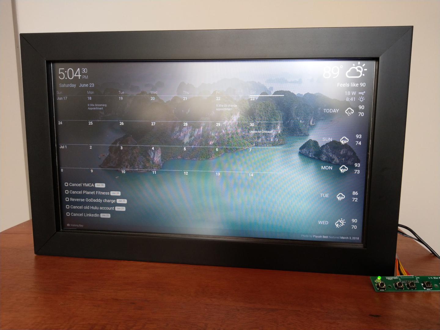
After adding the hard drive to my previous Raspberry Pi project and putting the RAM into a newer laptop, I still wasn’t sure what to do with the screen. Taking inspiration from the many “Magic Mirror” builds on the Raspberry Pi subreddit, I decided to make a digital family calendar out of it.
Making a Monitor
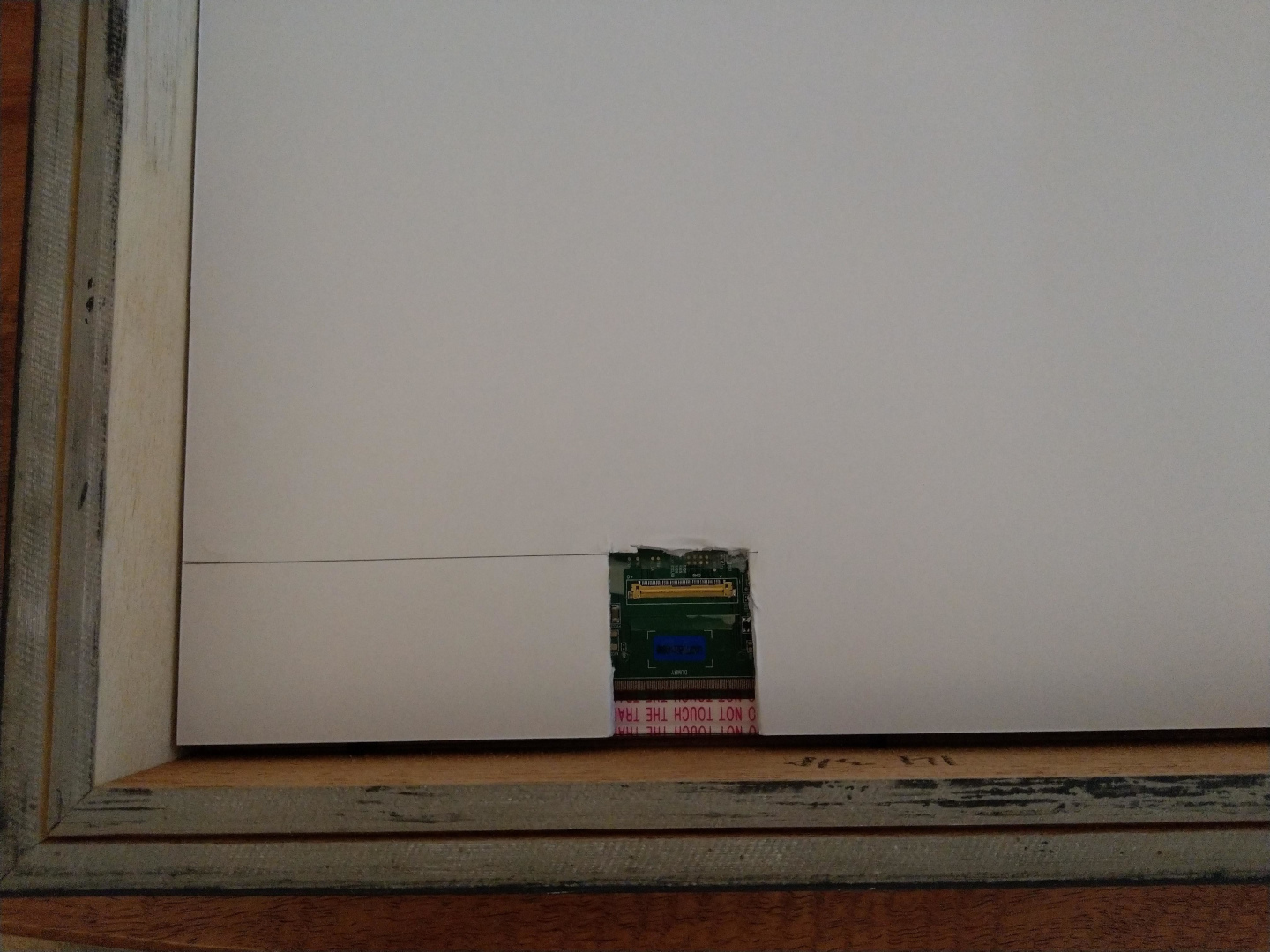
The first issue to solve here was actually connecting some device to the screen. The display panel itself only has a ribbon cable connector that used LVDS, which meant I had to special order an LCD controller to act as a middleman. Thankfully, the wonderful people at qstore made this easy – I gave them the model number for my LCD panel, and they sent me a controller that would work.
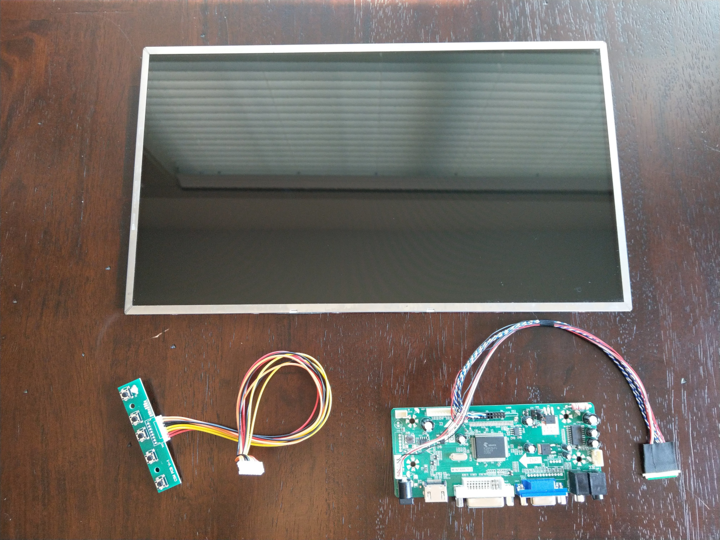
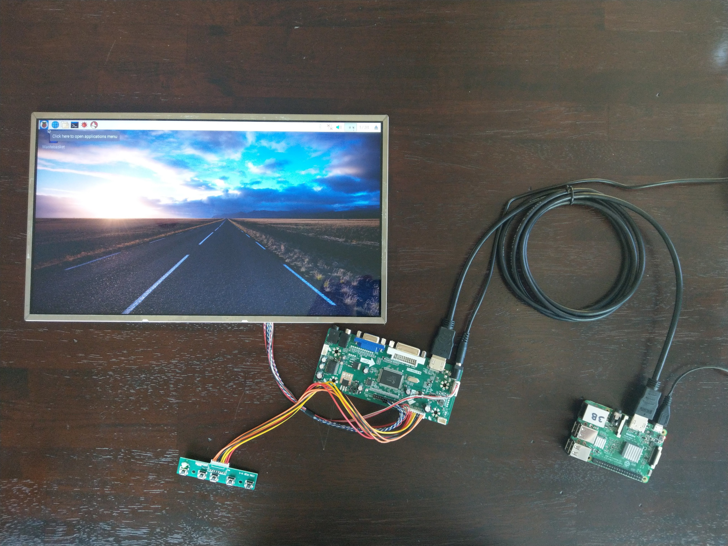
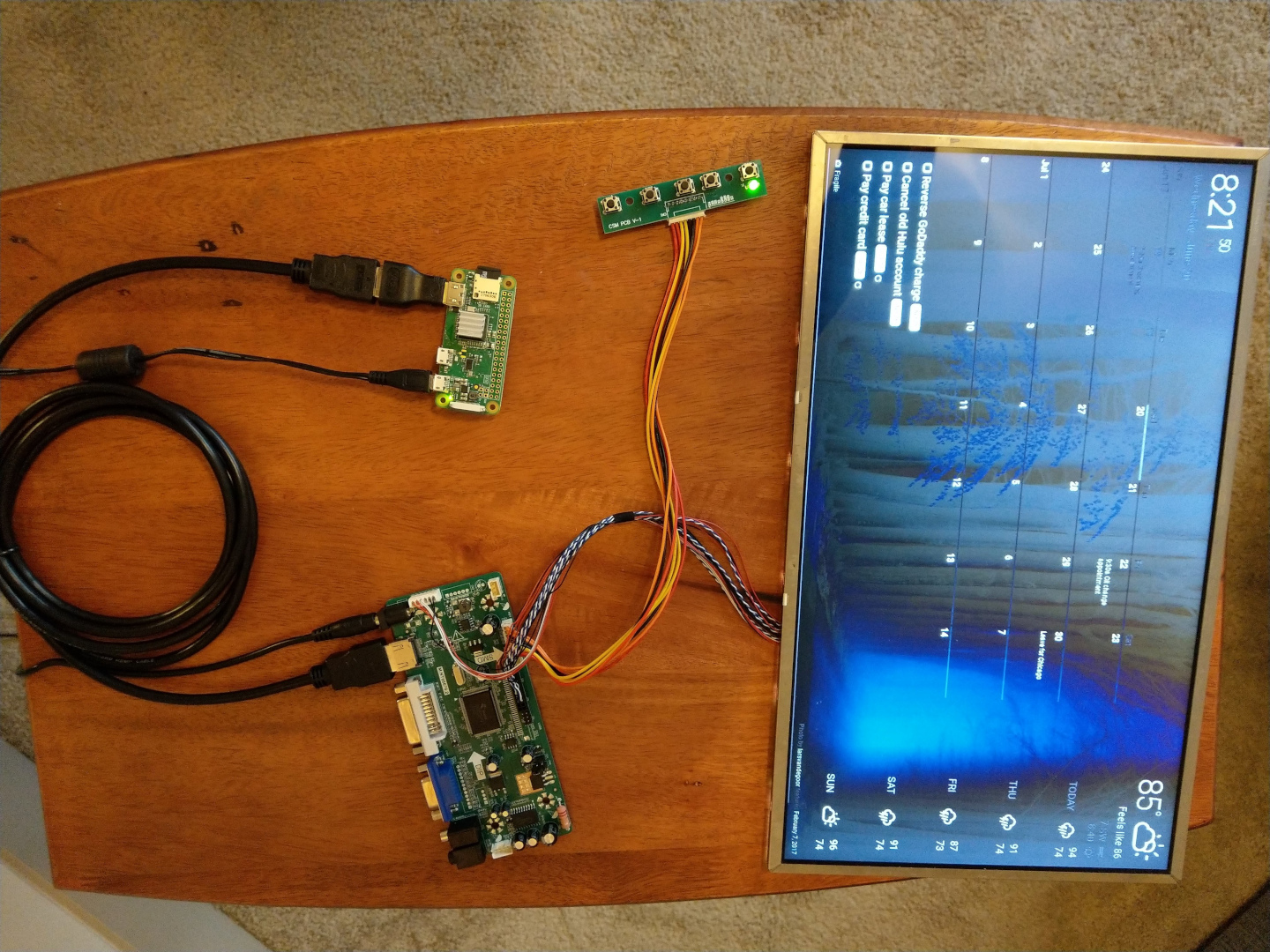
With all of the parts for the display together, it was time to test it. I plugged in a Raspberry Pi I had laying around and…
Creating the Calendar
This was, much to my suprise, the easiest part of the project. DAKboard allows anyone to create a clean, organized display connected to an external calendar, todo list program, and the local weather.
I should note here – the free tier of DAKboard’s service is fairly limited. Most people prefer to use the open-source MagicMirror project for this, but I did not as I’m using a Pi Zero as the computer for the calendar.
Finally, I had to tweak some config files to ensure the screen would stay on and the mouse wouldn’t be there all the time. Inside the /home/pi/.config/lxsession/LXDE-pi/autostart file, put the following code:
# These are the default entries, some commented out
@lxpanel --profile LXDE-pi
#@pcmanfm --desktop --profile LXDE-pi
#@xscreensaver -no-splash
#@point-rpi

# These set the screen to not sleep
@xset s off
@xset -dpms
@xset s noblank

# This opens a browser to your DAKboard view in fullscreen mode
@chromium-browser --noerrdialogs --incognito --kiosk https://dakboard.com/app/screenPredefined?p=<your_screen_id>
The URL for your screen can be found by going into the setting of your DAKboard screen, going to the “Settings & Defaults” tab, and looking in the “Private URL” field.
Next, I installed a program called unclutter that will cause the mouse to disappear after a few seconds of inactivity:
sudo apt install unclutterLast, and certainly not least, I used raspi-config to enable SSH and change the hostname of the Pi. This means I can easily log in to make changes without taking the whole setup off the wall.
Finding a Frame
In order to actually hang this on a wall for everyone to see, it needed a frame. This meant measuring the screen width and height, then figuring out how deep it needed to be to hide all of the computer components and cabling. Fun fact, the depth of a frame is called the “rabbet”.
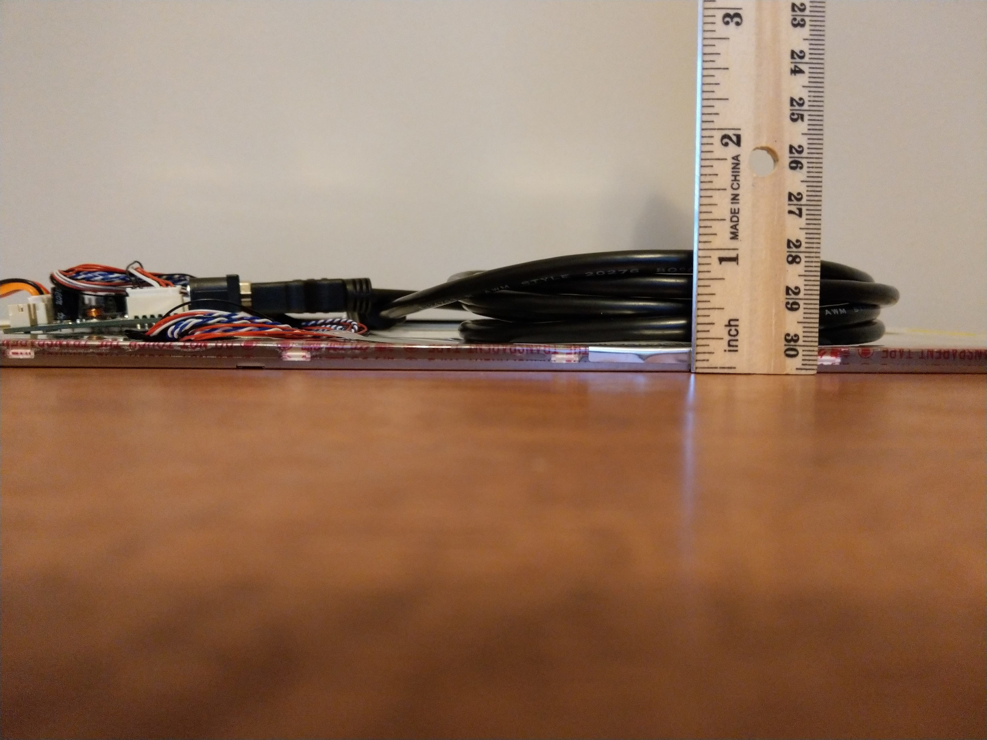
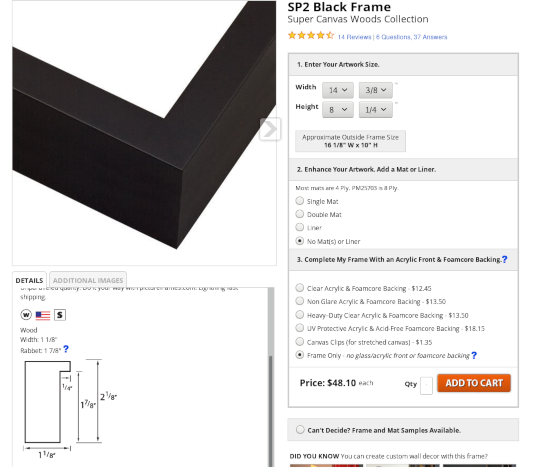
The entire thing came out to 14.375” wide, 8.25” tall, and almost exactly 1” deep. A quick search online led me to the aptly named pictureframes.com, which lets you order a custom-sized frame of your choosing. I found one that would look nice with the screen, had plenty of depth, and wasn’t bank-breakingly expensive.
Providing the Power
As luck would have it, I already had a 12V adapter that worked for the LCD controller, and I have more micro USB adapters than I know what to do with. This left me with a bit of an issue though – my mirror would have two separate power cables using two outlets. I had remembered another project using an extension cable to hide the other power components inside the frame, but this would further crowd behind the panel and add quite a bit of weight.
After posting some initial pictures on the Raspberry Pi subreddit, some commenters noted there are some 5V headers I could use to power the Pi from the controller board.
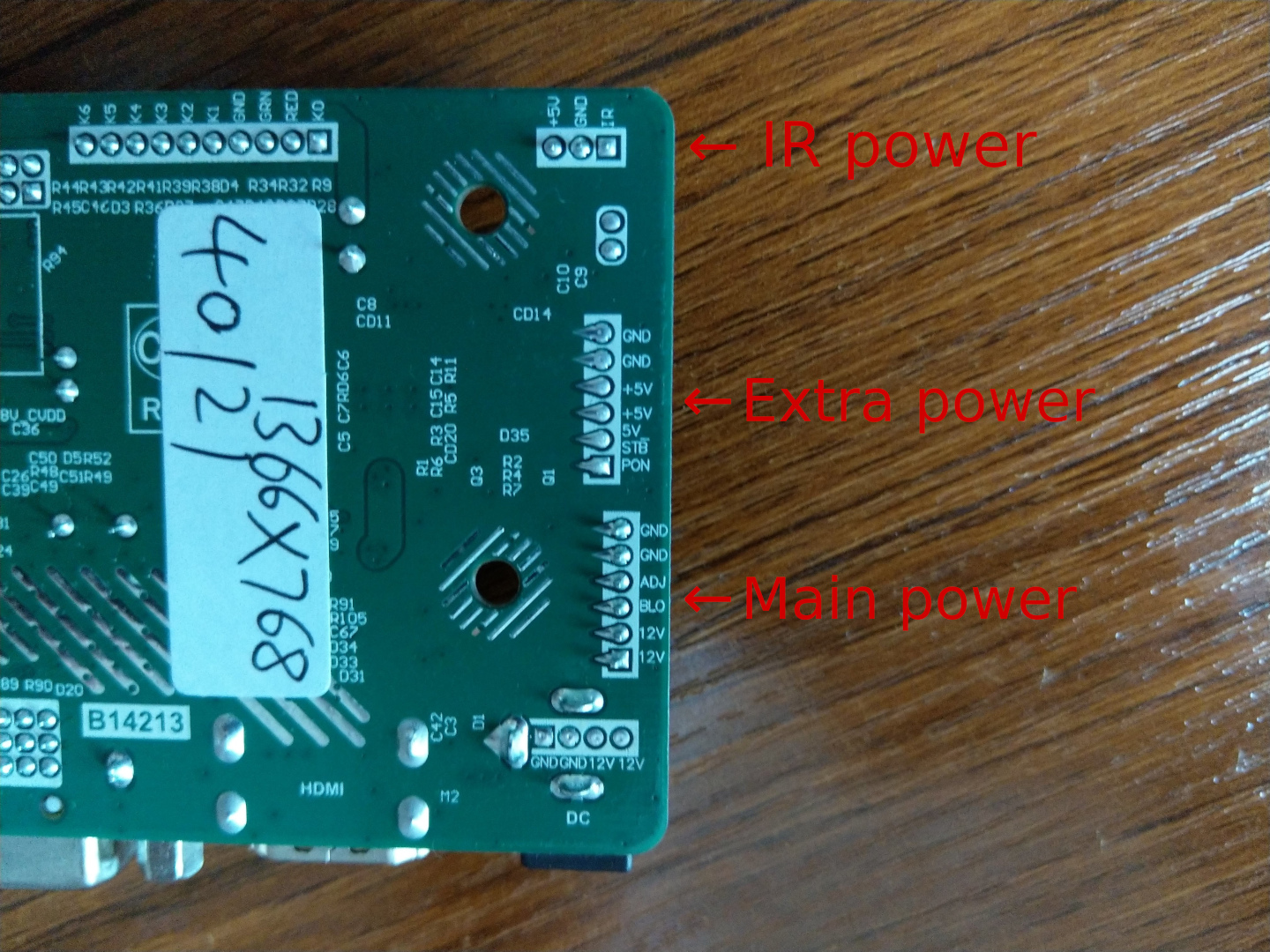
I stripped the USB side of an old micro USB cable to reveal the power and data lines within, pictured below. The colors are standard across almost all cables – red is 5V, black is ground, and white and green are data lines.
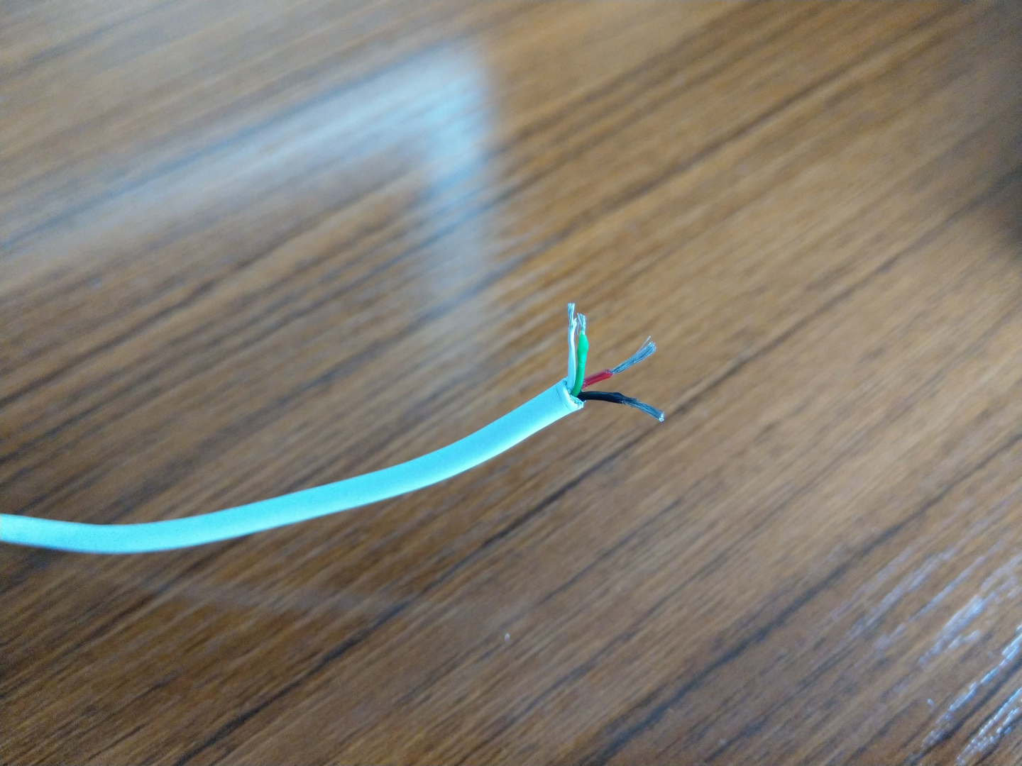
The idea is to solder the 5V and ground lines into their respective spots on the controller board, then plug the micro USB side of the wire into the Pi’s power port. This way, the only power cable needed is the 12V cable for the controller.
Putting It All Together
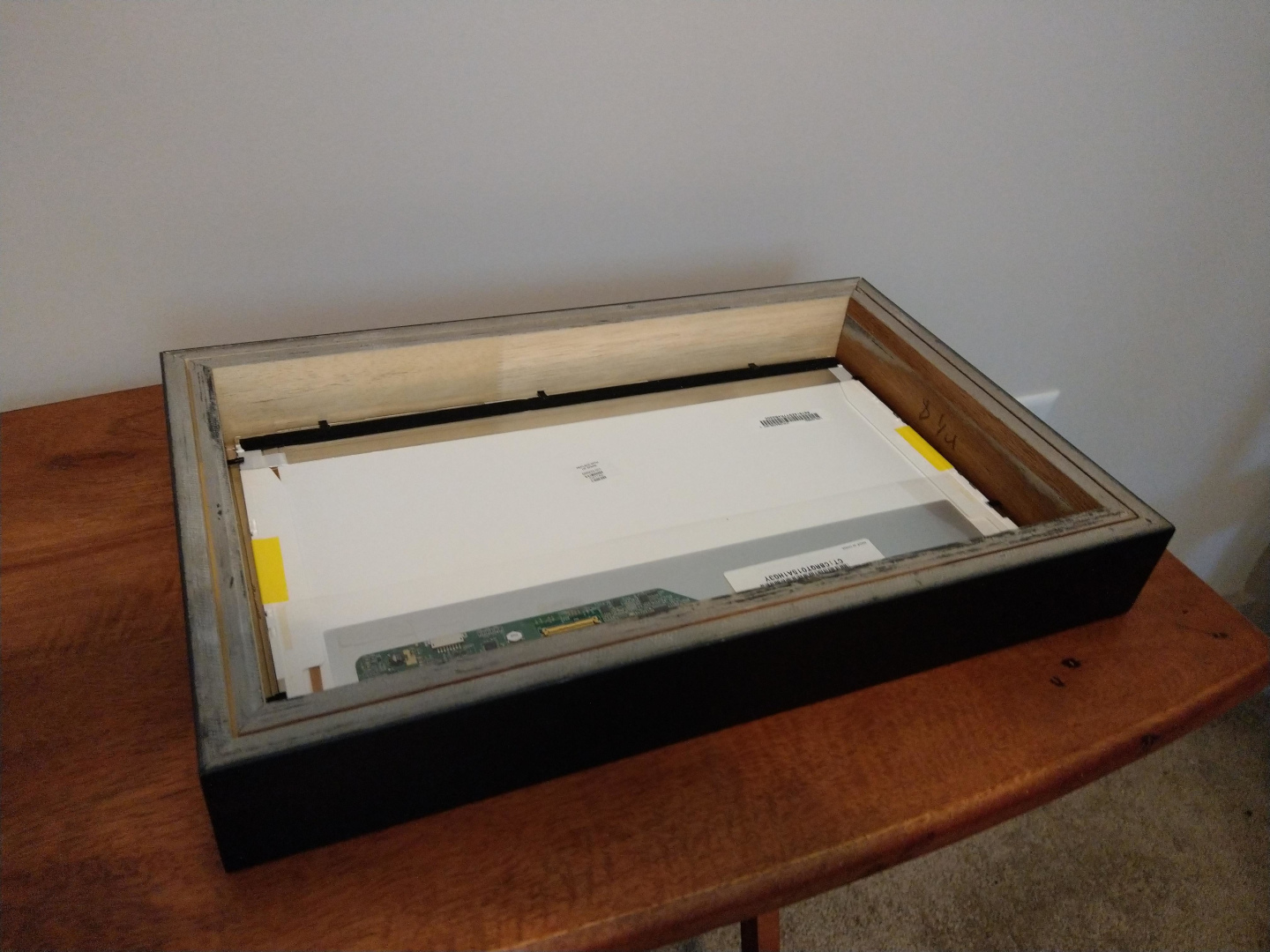
When the frame arrived a few days later, the frame fit almost perfectly inside. I did opt to get the acryllic front (my wife likes to touch screens) and the foamcore backing (so the Pi and the LCD controller aren’t sitting directly on the screen). So, I cut a hole in the foam back and set everything up inside the frame.
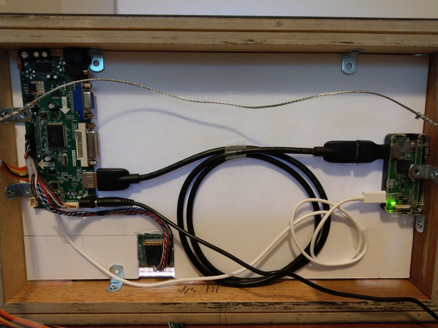
Next I used the brackets that came with the frame to pin down the Pi and the controller. For all of the cables I used tape to hold them in place.
The only things left after this were the finishing touches to make sure it looked nice hanging on the wall. This meant cutting notches in the back for the power cord and LCD control panel cord, attaching the control panel to the outside of the frame (I chose the bottom so it’s somewhat hidden), and adding the picture wire to hang it. All said and done, assembly of the frame took a little less than an hour.